Conformal cooling for die casting is the same concept as injection molding conformal cooling — channels that follow cavity geometry — but it operates in a far more demanding environment: aluminum melt at 680°C, injection pressures above 700 bar, and thermal shock cycles that would crack a poorly designed insert within 50,000 shots. This guide covers what changes when you move from injection molding to die casting applications, and how to design LPBF inserts that survive the difference.
1. Why Die Casting Demands Different Design Rules
Injection molding and die casting both involve injecting a molten material into a steel mold cavity and cooling it to ejection temperature. But the thermal and mechanical conditions are fundamentally different in three ways that directly affect conformal cooling insert design:
| Condition | Injection Molding | Aluminum Die Casting | Design Implication |
|---|---|---|---|
| Melt temperature | 200–350°C | 650–720°C | Higher thermal gradient → greater thermal stress at channel walls |
| Injection pressure | 150–200 bar | 700–1,500 bar | Heavier minimum wall thickness required (≥ 3 mm vs. ≥ 2 mm) |
| Thermal shock per cycle | Low (ΔT ≈ 150°C) | Severe (ΔT ≈ 500°C) | Must use stress-relief annealing; conservative bend radius (R ≥ 2×D) |
| Mold temperature (operating) | 20–180°C | 150–250°C | Higher background temperature reduces effective coolant ΔT |
| Surface erosion | Minimal | Significant (Al alloy erosion) | Hard coating (PVD nitriding) recommended on cavity surface |
| Insert shot life (conventional) | 500,000–2,000,000 | 100,000–400,000 | More frequent inspection cycles; conformal insert ROI must account for shorter life |
2. Material Selection for Die Casting Conformal Inserts
The material choices for die casting conformal inserts are narrower than for injection molding. The severe thermal cycling eliminates low-toughness options and demands materials with both high hot hardness and thermal fatigue resistance:
| Material | Hot Hardness (600°C) | Thermal Conductivity | LPBF Printability | Recommendation |
|---|---|---|---|---|
| H13 Tool Steel | 28–32 HRC | 28 W/m·K | Good (requires controlled atmosphere) | Primary choice for aluminum die casting |
| 18Ni300 Maraging Steel | 36–40 HRC | 20 W/m·K | Excellent | Good for zinc/magnesium die casting; lower thermal shock resistance than H13 |
| 420 Stainless Steel | 22–26 HRC | 24 W/m·K | Excellent | Not recommended for aluminum; insufficient hot hardness |
| CuCrZr | 15–18 HRC | 320 W/m·K | Good | Hot spots only; small inserts in non-erosion zones; very short life |
3. Conservative Design Rules for Die Casting
All parameters from injection molding conformal cooling design are scaled up for die casting's more demanding conditions:
| Parameter | Injection Molding (reference) | Die Casting (required) | Reason for Increase |
|---|---|---|---|
| Min. wall thickness (channel to cavity) | ≥ 2.0 mm | ≥ 3.0 mm | 700+ bar injection pressure; thermal fatigue accumulation |
| Channel diameter | 6–12 mm | 8–14 mm | Higher flow rates needed to handle greater heat load; avoid scale risk at smaller diameters |
| Channel pitch (center-to-center) | 2.0–3.0 × D | 2.5–3.5 × D | More steel between channels for structural integrity under pressure cycling |
| Bend radius | ≥ 1.5 × D | ≥ 2.0 × D | Reduced stress concentration at bends under thermal cycling |
| Post-processing | Stress relief + heat treatment | Stress relief + HIP + heat treatment | HIP mandatory to close micro-porosity before high-pressure service |
| Pressure test (pre-deployment) | 200 bar × 30 min | 500 bar × 60 min | Must verify at 30–50% above operating pressure |
4. Heat Load Calculation for Die Casting
Sizing the cooling circuit for die casting requires quantifying the heat load per cycle. The calculation differs from injection molding because the metal enthalpy is much higher:
Aluminum alloy (A380) heat content calculation:
- Injection temperature: 680°C
- Ejection temperature: 250°C (typical)
- Enthalpy change ΔH ≈ 560 kJ/kg (includes latent heat of solidification)
- Casting weight: 0.8 kg
- Heat to be extracted per shot: 0.8 × 560 = 448 kJ
- Cycle time: 45 seconds → heat flux: 448/45 = 9.95 kW per cavity
Compare to a typical injection molded PA66 part (0.3 kg, ΔH ≈ 150 kJ/kg, 28s cycle): 0.3 × 150 / 28 = 1.6 kW. Die casting generates roughly 6× more heat per cavity — confirming why die casting cooling systems require much higher coolant flow rates and why the thermal design of conformal channels is more challenging.
5. Cycle Time in Die Casting: What Conformal Cooling Can and Cannot Do
In injection molding, the cooling phase often represents 50–65% of total cycle time, making it the dominant target for improvement. In die casting, the cycle time distribution is different:
| Phase | Typical Duration | % of Cycle | Conformal Cooling Impact |
|---|---|---|---|
| Die close + inject | 2–4 sec | 5–10% | None |
| Intensification | 3–6 sec | 7–13% | None |
| Cooling / solidification | 12–20 sec | 30–45% | Primary target: −30–40% of cooling phase |
| Die open + ejection | 4–6 sec | 10–13% | None |
| Spray + reset | 10–18 sec | 25–40% | None (die spray time fixed) |
Because cooling is only 30–45% of total die casting cycle (vs. 50–65% in injection molding), and conformal cooling reduces only the cooling phase, total cycle time reduction is limited to approximately 10–20% even with highly effective conformal channels. This is still valuable — a 15% reduction on a 45-second cycle is 6.75 seconds per shot, representing significant throughput at high volume — but expectations must be calibrated correctly compared to injection molding results.
6. Application Cases: Where Conformal Cooling Delivers in Die Casting
Automotive Structural Die Castings
Part examples: Transmission housings, subframe brackets, battery enclosures, motor mounts
Challenge: Thick sections (15–40 mm) cool slowly with conventional straight channels; porosity near the thermal center
Conformal benefit: Channels wrap around thick sections maintaining closer proximity, reducing hot spot temperature by 80–120°C
Cycle time result: −12–18% overall; porosity rate reduced 40–60%
Thin-Wall Enclosures (Consumer Electronics)
Part examples: Laptop frames, camera bodies, audio device housings
Challenge: Wall thickness 1.5–3 mm; need dimensional accuracy ±0.05 mm with no warpage
Conformal benefit: Temperature uniformity across the thin wall prevents differential contraction; ΔT reduced from 45°C to 8°C
Cycle time result: −15–20%; dimensional rejection rate −70%
Zinc Alloy Die Casting (Zamak)
Part examples: Locks, hardware fittings, decorative trim
Challenge: Lower melt temperature (420°C) makes this the most accessible die casting application for conformal cooling; highest cycle frequency (5–8 sec cycles)
Conformal benefit: Even small cycle time reductions (1–2 sec at 5-sec cycle = −20–40%) deliver very fast payback
Cycle time result: −18–28% overall
7. Maintenance and Inspection Schedule
Die casting inserts face more aggressive wear than injection mold inserts. Conformal cooling inserts in die casting require a more frequent inspection schedule:
| Inspection Item | Interval | Accept / Replace Criterion |
|---|---|---|
| Cavity surface wear (dimensional CMM) | Every 25,000 shots | Dimension deviation > ±0.1 mm → re-machine or replace |
| Channel pressure integrity test | Every 50,000 shots | Any pressure drop below 400 bar after 30 min → replace |
| Surface crack inspection (penetrant) | Every 50,000 shots | Any crack > 5 mm at gate area → replace |
| Hardness verification | Every 100,000 shots | H13 below 40 HRC → re-heat treat or replace |
| Flow rate verification | Every 10,000 shots | Flow rate below minimum for Re > 10,000 → clean or replace |
8. Frequently Asked Questions
Can conformal cooling be used in die casting molds?
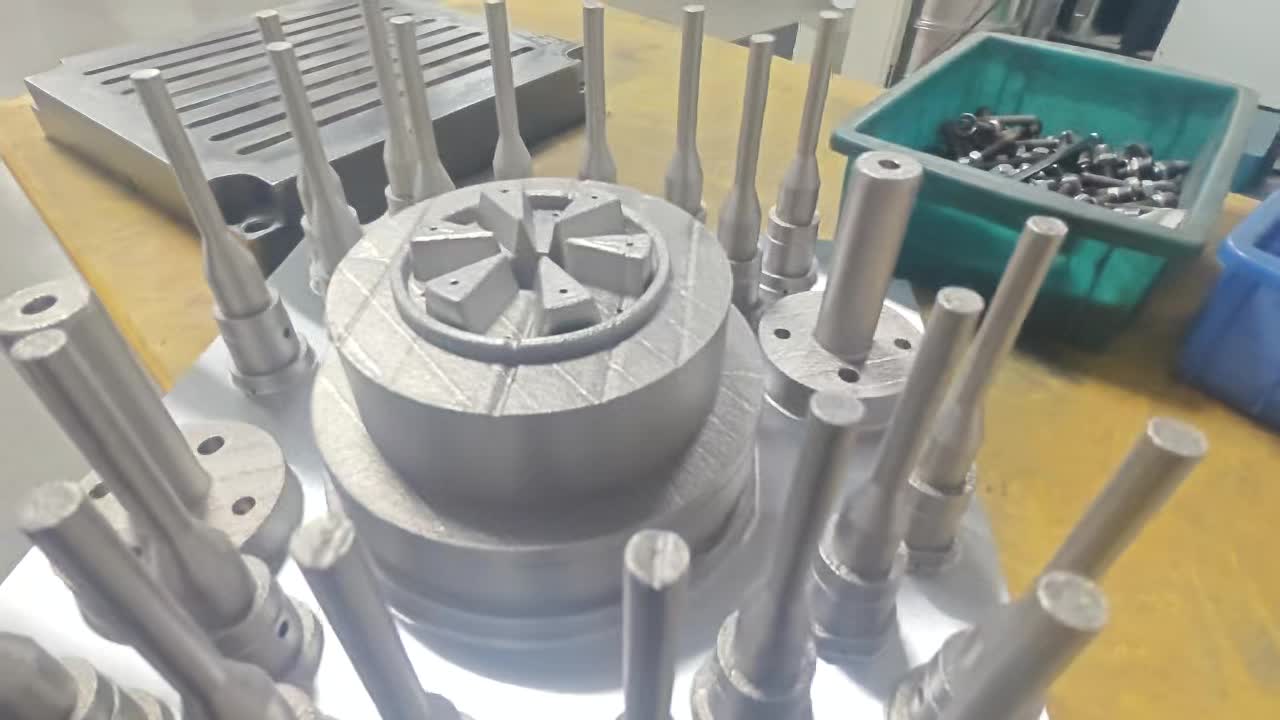
Yes. LPBF-manufactured conformal cooling inserts are commercially used in aluminum, zinc, and magnesium die casting. The design rules are more conservative than injection molding (≥ 3 mm wall thickness, R ≥ 2×D bends, mandatory HIP post-processing), and the material must be H13 or maraging steel. Properly designed inserts achieve 150,000–300,000 shots before refurbishment in aluminum die casting.
Why is die casting harder than injection molding for conformal cooling?
Three factors: aluminum melt enters at 650–720°C (vs. 200–350°C for plastics), creating far more thermal shock per cycle; injection pressures exceed 700 bar (vs. 150–200 bar for plastics), requiring heavier channel walls; and aluminum alloy erodes the cavity surface faster than plastic, reducing insert service life. These factors require more conservative design parameters and mandatory HIP post-processing to eliminate porosity before high-pressure service.
What cycle time reduction is achievable in die casting?
15–30% reduction of the cooling phase, translating to 10–20% overall cycle time reduction — less than injection molding because die spray and ejection mechanics represent a larger fixed proportion of die casting cycle time. Still economically significant at high production volumes.
Conformal Cooling for Your Die Casting Mold
MouldNova engineers LPBF conformal inserts in H13 and maraging steel for aluminum, zinc, and magnesium die casting. Submit your cavity drawing for a free thermal simulation and quote.
Request Die Casting Quote →