- Series vs. parallel circuit layout: which to choose and when
- Channel diameter selection: 6, 8, or 10mm — the correct logic
- Pitch (channel-to-channel spacing) and offset (wall distance from cavity surface)
- Flow rate, velocity, and Reynolds number — achieving and confirming turbulent flow
- Pressure drop calculation across a conformal cooling circuit
- How to identify and eliminate dead zones (areas of stagnant or low-flow coolant)
- Channel cross-section shapes: round vs. teardrop vs. diamond
- Cleaning and long-term maintenance of conformal cooling lines
Table of Contents
Series vs. Parallel Circuit Layout
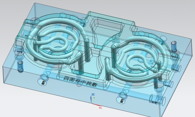
The single most consequential layout decision in conformal cooling line design is whether to connect channels in series (one long continuous path from IN to OUT) or in parallel (multiple shorter paths running simultaneously between a shared manifold).
Series Circuit
- One continuous serpentine channel from a single IN to a single OUT
- Simple plumbing — two connections per insert only
- Coolant heats progressively along the circuit — the outlet end receives warmer coolant than the inlet, creating a temperature gradient across the insert (ΔT of coolant itself)
- Pressure drop is the sum of all channel segments in series — can become very high for long circuits (>1.5 bar for circuits longer than 800mm in 8mm channel)
- Best for: inserts with cavity area < 100×100mm, or where simplicity of plumbing is the priority
- Typical total channel length: 300–800mm before pressure drop becomes limiting
Parallel Circuit
- Multiple shorter channel paths run simultaneously between a common inlet manifold and common outlet manifold
- Each branch sees the same inlet temperature — no cumulative heating effect along the circuit
- Overall pressure drop is the pressure drop of a single branch (much lower than equivalent series circuit)
- Allows independent flow control per zone if different circuits feed thermally distinct areas
- Requires more plumbing connections — typically 2×N connections for N parallel branches
- Best for: inserts with cavity area >100×100mm, long narrow inserts (core pins), or any application where temperature uniformity is critical
- Risk: flow imbalance between parallel branches if branches have different resistance — requires balanced design or individual flow meters
For parallel circuits, branch flow balance is critical. If two branches have different hydraulic resistance, flow will preferentially follow the lower-resistance path — leaving the high-resistance branch with insufficient flow and potentially laminar conditions. Design all parallel branches to the same total channel length and the same number of bends. Where geometry prevents this, use a orifice plate or needle valve on the lower-resistance branches to impose deliberate restriction.
Channel Diameter Selection
Channel diameter is the single most important design variable after channel position. It determines flow area, turbulence threshold flow rate, pressure drop per unit length, and SLM printability. The choice is not arbitrary — it must be calculated for your specific insert size and flow conditions.
Why 8mm is the industry standard
An 8mm diameter channel achieves turbulent flow (Re > 4,000) at a flow velocity of approximately 0.5 m/s, which corresponds to a flow rate of just 1.5 L/min. This is well within the capability of any standard chiller or mold temperature controller. At the same time, pressure drop per metre of channel is manageable (approximately 0.06 bar/m at this flow rate for water at 25°C), allowing circuits up to 500mm long before exceeding a practical 0.3 bar pressure drop budget per circuit.
A 6mm channel requires higher velocity to achieve turbulence — approximately 0.8 m/s (2.3 L/min) for Re = 4,000 — but the smaller bore means pressure drop per metre is significantly higher (approximately 0.18 bar/m). Use 6mm channels only in short circuits or when the tight pitch constraint forces it.
Diameter and wall thickness interaction
Channel diameter must be sized against available wall thickness. The minimum wall between any channel surface and the cavity face should be 1.0×D (8mm for an 8mm channel). The minimum wall between adjacent channels should be 0.5×D (4mm for 8mm channels). Violating these minimums creates structural integrity risks in the SLM-printed insert under injection pressure.
Pitch and Offset from Cavity Surface
Pitch and offset together define the spatial density of cooling coverage at the cavity surface. Both must be specified precisely — vague terms like "close to the surface" or "uniformly spaced" are not engineering specifications.
| Parameter | Definition | Recommended Range | Consequence if Wrong |
|---|---|---|---|
| Offset (wall distance) | Distance from channel centerline to cavity surface | 8–15mm (target: 1.0–1.5×D) | Too close: structural risk, flash; Too far: approaches conventional cooling performance |
| Pitch (channel spacing) | Center-to-center distance between adjacent parallel channels | 12–20mm for 8mm channel (target: 1.5–2.5×D) | Too close: pressure drop increase, print cost; Too far: temperature non-uniformity between channels |
| Pitch-to-offset ratio | Pitch divided by offset | <2.0 for good uniformity | Ratio >2.0 creates visible "scalloping" pattern in thermal map |
| Bend radius | Radius of channel path curvature at turns | ≥1.5×D (12mm minimum for 8mm channel) | Tight bends increase pressure drop and create low-velocity zones at the inside of bends |
The pitch-to-offset rule in practice
If pitch = 20mm and offset = 10mm, the ratio is 2.0 — at the acceptable limit. The temperature at the cavity surface directly between two channels will be approximately 2–4°C higher than directly above a channel (the "scalloping" effect). This is acceptable for most commercial parts but may not meet the <2°C uniformity required for optical or medical parts.
To achieve <2°C uniformity, target a pitch-to-offset ratio of 1.5 or below — e.g., 12mm pitch with 8mm offset. This is a denser and more expensive channel network but delivers near-isothermal cavity surface conditions.
Flow Rate, Velocity, and Reynolds Number
Turbulent flow is not optional for effective conformal cooling — it is a fundamental requirement. Laminar flow in a conformal cooling channel delivers cooling performance that is barely better than a conventional straight-drilled channel, because the heat transfer coefficient in laminar flow is 5–10× lower than in turbulent flow at the same velocity.
Reynolds number calculation
Practical flow rates for turbulent flow
| Channel Diameter | Min. Flow for Re=4000 | Recommended Flow (Re=6000) | Max. Practical Flow (Re=10000) |
|---|---|---|---|
| 6mm | 1.4 L/min | 2.1 L/min | 3.5 L/min |
| 8mm (standard) | 1.9 L/min | 2.8 L/min | 4.7 L/min |
| 10mm | 2.4 L/min | 3.5 L/min | 5.9 L/min |
Values for water at 25°C. Flow rates scale approximately linearly with channel cross-section area. For chilled water at 10°C, minimum turbulence flow rates are approximately 20% lower due to reduced kinematic viscosity.
Pressure Drop Calculation
Every conformal cooling circuit has a hydraulic resistance that determines the pressure required from the chiller to achieve the target flow rate. Designing circuits that exceed the chiller's pressure capability renders the conformal cooling design non-functional in production.
Pressure drop in a conformal cooling channel is calculated using the Darcy-Weisbach equation:
Practical pressure drop budget
Design each cooling circuit to have a pressure drop below 0.5 bar at the target flow rate. Most mold temperature controllers provide 4–8 bar pump pressure; a circuit pressure drop of 0.5 bar leaves ample margin for fitting losses (typically 0.1–0.2 bar total for standard fittings and hoses) and pressure variation between shots.
For a series circuit of 500mm total length in 8mm channel at 2.8 L/min (Re = 6,000), with SLM surface roughness (f ≈ 0.028), the calculated pressure drop is approximately 0.13 bar — well within budget. A 1,500mm series circuit at the same flow rate would reach 0.39 bar — still acceptable but approaching the limit. Longer circuits should be split into parallel branches.
Eliminating Dead Zones
A dead zone in a conformal cooling circuit is any region where coolant velocity falls close to zero — either because the channel terminates in a blind end, because a T-junction creates a stagnant branch, or because a section of channel is geometrically downstream of a short-circuit path and therefore receives negligible flow.
Common dead zone sources and fixes
- Blind-end channels: Never design a channel that terminates without an exit. Every channel segment must have a continuous flow path from IN to OUT. If a feature geometry forces a dead-end (e.g., cooling into a sharp corner), use a baffle plug machined post-SLM to redirect flow back out of the dead end zone.
- T-junctions without return paths: A T-junction where flow enters from the stem and splits into two branches with one branch flowing significantly less than the other creates a quasi-dead zone in the low-flow branch. Size branches to equal hydraulic resistance, or install a flow-restriction fitting on the higher-flow branch to balance the split.
- Outer bends in curved inserts: In a curved conformal channel (following a mold surface with significant curvature), the outer radius of the channel bend sees lower velocity than the inner radius. In sharp bends, the outer-radius flow can become transitional or laminar. Maintain bend radius ≥1.5×D to limit velocity non-uniformity to <15% across the channel cross-section.
- Parallel branch imbalance: In parallel circuits, if one branch has 2× the hydraulic resistance of another, the low-resistance branch carries ∼60% of total flow and the high-resistance branch carries ∼40% — below the target. At worst, the high-resistance branch drops below turbulence threshold. Balance branch lengths and bend counts.
Channel Cross-Section Shapes
Conformal cooling lines in SLM-printed inserts can be produced in multiple cross-section profiles, each with distinct thermal, hydraulic, and printability characteristics:
Teardrop (Drop-Shaped)
Round bottom half, pointed top (like a raindrop inverted). The pointed crown is self-supporting during SLM printing when printed with the point facing up — no internal supports needed. Hydraulically close to round. Best combination of printability and thermal performance.
Round (Circular)
Standard geometry. Optimal hydraulic performance (minimum pressure drop for a given flow area). However, the top of the circle (the roof of the internal bore) is an overhang during SLM printing — requires a print angle <45° from vertical to be self-supporting, or requires internal support structures (which must then be removed).
Diamond / Rhombus
Four flat faces oriented at 45° diagonals. Fully self-supporting in any orientation during SLM printing (all faces at ≥45° from horizontal). Slightly lower heat transfer than round at equivalent hydraulic diameter due to corner stagnation zones, but avoids all overhang concerns. Used in complex-curved inserts where channel orientation varies widely.
In practice, most conformal cooling suppliers use the teardrop profile as the default and the diamond profile for geometrically complex inserts where channel orientation cannot be controlled. Round channels are used when the designer can guarantee build orientation keeps the bore roof below 45° from horizontal throughout — or when the supplier has accepted the risk of internal support removal.
Cleaning and Maintenance of Conformal Cooling Lines
Conformal cooling lines require two distinct types of maintenance attention: post-manufacture cleaning (removing sintered powder from the SLM printing process) and in-service maintenance (preventing and removing scale deposits during production life).
Post-SLM powder removal
Sintered metal powder trapped in conformal cooling channels during SLM printing is one of the most significant quality risks in the process. Powder that is not removed before the insert enters service will: (1) partially block the channel, reducing flow and turbulence; (2) continue sintering under the heat of production, eventually cementing into solid blockages; and (3) potentially migrate into the coolant circuit, damaging the chiller pump. The detailed powder removal procedure is covered in our dedicated article on cleaning powder from conformal cooling lines. The mandatory steps are: forced air purging at ≥6 bar, ultrasonic cleaning, re-purging, and borescope verification of clear bore before pressure testing.
In-service scale management
In production, the main maintenance concern is calcium carbonate and magnesium carbonate scale deposition from hard process water. Scale builds up on the channel internal walls at approximately 0.1–0.3mm per year in untreated water with hardness >150 ppm CaCO&sub3;. At 0.5mm scale thickness, the flow area of an 8mm channel is reduced by approximately 12%, and heat transfer is reduced by 15–25% (scale has thermal conductivity of only 1–3 W/m·K vs. 15–20 W/m·K for steel).
Prevention is more effective than remediation:
- Use deionised or softened water in the coolant circuit — this eliminates scale almost entirely
- Use chemical inhibitors (glycol-based or specific mold cooling inhibitors) to prevent both scale and corrosion
- Annual chemical descaling with 5% citric acid solution circulated for 2–4 hours removes scale without damaging 420 SS or 18Ni300 insert materials. Do not use hydrochloric acid — it attacks the chromium passive layer in stainless steel.
- Pressure test annually: after any descaling treatment, re-pressure-test the circuit at 1.5× operating pressure for 10 minutes before returning to production.
Get Your Conformal Cooling Line Design Validated
MouldNova's engineering team provides full channel layout design, Moldflow simulation validation, and a pressure-tested insert — with Reynolds number and pressure drop calculations included in every project report.
Frequently Asked Questions
What is the correct channel diameter for conformal cooling lines?
What Reynolds number should conformal cooling channels target?
What is the correct pitch and offset for conformal cooling lines?
How do you clean and maintain conformal cooling lines after SLM printing and in production?
Related Articles & Pages
- Conformal Cooling Channel Design: Parameters & Engineering Workflow
- Conformal Cooling Simulation: Setup, Results Interpretation & When to Trust Them
- Cleaning Powder From Conformal Cooling Channels After SLM Printing
- Conformal Cooling Mold Design: Engineering Guide for 2026
- Conformal Cooling Mold: Complete Buyer's Guide — Types, Pricing, Supplier Evaluation
- Conformal Cooling Design: Decision Framework & Application Guide
- Injection Mold Cooling System: Design, Optimization & Troubleshooting
- Our Conformal Cooling Insert Service — Get a Quote