1. What Is Metal Additive Manufacturing?
Metal additive manufacturing (metal AM) is a family of industrial manufacturing processes that build fully solid metal parts by depositing and fusing material layer by layer, directly from a digital 3D CAD model. Unlike subtractive manufacturing (CNC machining), which cuts material away from a block, or formative manufacturing (casting, forging), which shapes material inside a mold, metal AM creates parts by adding material only where it is needed — enabling geometries that are impossible to produce any other way.
The term "additive manufacturing" comes from the ISO/ASTM 52900 standard and is the formal engineering name for what is commonly called 3D printing. When applied specifically to metals — steel, titanium, aluminum, Inconel, copper — it becomes metal additive manufacturing, or metal AM for short.
Metal AM is not a single process. It encompasses at least five distinct technology families, each with different energy sources, feedstock types, and trade-offs. The most widely used for precision parts is Laser Powder Bed Fusion (LPBF), also known as Selective Laser Melting (SLM) or Direct Metal Laser Sintering (DMLS). These names refer to essentially the same process — a high-power laser selectively melts metal powder one layer at a time to build up a solid part.
Metal AM has been commercially available since the mid-1990s and is now used across aerospace, medical, automotive, energy, and industrial tooling sectors. The global metal AM market exceeded $17 billion in 2026, driven by applications where the technology delivers clear advantages over conventional manufacturing: complex internal geometries, lightweight topology-optimized structures, and rapid production of low-volume parts without tooling investment.
For a beginner-friendly overview of whether metals can actually be 3D printed (and what the output looks like), see our guide: Can You 3D Print Metal?
2. How Metal Additive Manufacturing Works
While each metal AM technology has a different mechanism, the general workflow is the same: prepare a digital 3D model, slice it into thin cross-sectional layers, and then build the part layer by layer using an energy source to fuse metal feedstock. Here is the step-by-step process for LPBF/SLM, the most widely used method:
The process starts with a 3D CAD model (typically in STEP format). Specialized software orients the part on the build platform, generates support structures for overhanging features, and slices the model into layers — typically 20 to 60 micrometers thick. Build parameters (laser power, scan speed, hatch spacing) are assigned based on the material.
A recoater blade spreads a thin, uniform layer of metal powder — particles 15 to 45 micrometers in diameter — across the build platform. The entire build chamber is sealed and purged with inert gas (argon or nitrogen) to prevent oxidation of the hot metal during melting.
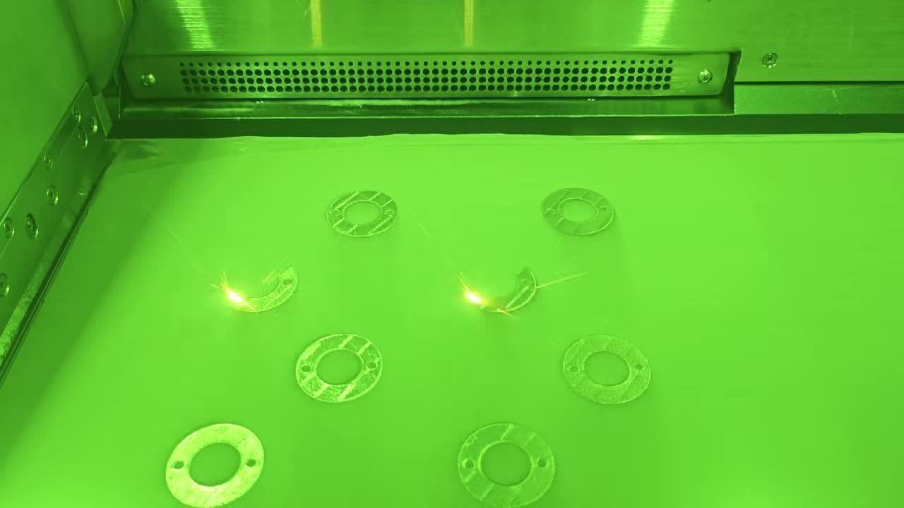
A high-power fiber laser (200 W to 1 kW) scans across the powder bed, melting and fusing the powder in the shape of that layer's cross-section. The laser is directed by a galvanometer mirror system at scan speeds of 500 to 2,000 mm/s. Modern machines use up to four lasers simultaneously to increase throughput. Unfused powder remains loose and acts as natural support.
The build platform lowers by one layer thickness. A new powder layer is spread. The laser scans again. This cycle repeats hundreds to thousands of times. A 50 mm tall part built at 40 µm layers requires 1,250 individual cycles. Total build times range from a few hours for small parts to several days for large or complex builds.
After the build completes, parts undergo stress relief heat treatment, support structure removal, and CNC machining of critical surfaces. Additional steps may include Hot Isostatic Pressing (HIP) to close residual porosity, surface finishing (bead blasting, polishing), and quality inspection (CMM, CT scanning). For tooling applications, age hardening brings the material to its final hardness.
For a more detailed walkthrough of LPBF specifically, including laser parameter settings and support strategy, see: Conformal Cooling & 3D Printing.
3. Metal AM Technologies Compared
There are five main metal additive manufacturing technologies in commercial use today. Each has different strengths, and the right choice depends on your part size, material, accuracy requirements, and production volume.
| Technology | Energy Source | Feedstock | Accuracy | Best For |
|---|---|---|---|---|
| LPBF / SLM | Fiber laser | Metal powder (15–45 µm) | ±0.05–0.1 mm | Precision parts, tooling inserts, complex geometries |
| EBM | Electron beam | Metal powder (45–105 µm) | ±0.2–0.3 mm | Titanium aerospace and medical parts, low residual stress |
| Binder Jetting | None (sintering furnace) | Metal powder + liquid binder | ±0.2 mm (after sintering) | Medium-to-high volume small parts, cost-sensitive applications |
| DED / WAAM | Laser, arc, or e-beam | Metal wire or powder | ±0.5–1.0 mm (needs machining) | Very large parts, component repair, adding features to existing parts |
| Metal FDM | None (sintering furnace) | Metal-filled filament or rods | ±0.2 mm (after sintering) | Office-friendly prototyping, low-stress functional parts |
LPBF / SLM — The Industry Standard
Laser Powder Bed Fusion is the most widely adopted metal AM process, accounting for roughly 80% of all metal AM parts produced worldwide. It delivers the best combination of accuracy, surface finish, and mechanical properties. LPBF is the technology of choice for injection mold inserts with conformal cooling channels, aerospace brackets, and medical implants. Machine brands include EOS, SLM Solutions, Trumpf, Renishaw, and Nikon SLM. For more on the SLM vs. DMLS naming distinction, see our SLM vs. DMLS comparison.
EBM — Electron Beam Melting
EBM uses an electron beam in a vacuum chamber and preheats the entire powder bed to 700–1,000°C. This dramatically reduces residual stress, making EBM ideal for crack-prone materials like titanium and nickel superalloys. Surface finish is rougher than LPBF (Ra 25–35 µm vs. Ra 5–15 µm), so post-machining is almost always required. GE Additive (Arcam) is the dominant EBM equipment maker.
Binder Jetting — Speed and Volume
Binder jetting skips the laser entirely. An inkjet head deposits a liquid binding agent onto each powder layer. The "green" part is then sintered in a furnace, shrinking 15–20%. Build speeds are 5 to 10 times faster than LPBF, making binder jetting attractive for production volumes of hundreds to thousands of small parts. Desktop Metal, ExOne (now part of Desktop Metal), and HP Metal Jet are leading systems.
DED / WAAM — Large-Scale and Repair
Directed Energy Deposition feeds metal wire or powder into a focused energy source (laser, plasma arc, or electron beam) and deposits it onto a substrate. Build volumes can exceed 1 meter. DED excels at repairing worn turbine blades, adding features to existing forged parts, and producing large structural components for aerospace and marine. Resolution is low — all functional surfaces require CNC finishing.
Metal FDM — Accessible Entry Point
Metal FDM (bound metal deposition) works like a desktop plastic 3D printer but uses metal-loaded filament. After printing, parts are debound and sintered. Machines cost $100,000–$200,000 (vs. $500,000+ for LPBF), making this the most accessible metal AM technology. Part density reaches 96–99%, which is acceptable for prototypes and low-stress applications but not for demanding structural or tooling use. Markforged Metal X and Desktop Metal Studio are the main brands.
4. Materials for Metal Additive Manufacturing
Over 50 metal alloys are commercially available as AM-ready powder or wire. The table below covers the most commonly used materials, their key properties, and typical applications. For a deeper dive into materials specifically for mold tooling, see our conformal cooling materials guide.
| Material Family | Common Grades | Key Properties | Typical Applications |
|---|---|---|---|
| Tool Steels | H13, MS1 (1.2709 maraging), M2 | 50–54 HRC hardness, high wear resistance | Injection mold inserts, die casting dies, cutting tools |
| Stainless Steels | 316L, 17-4 PH, 304L, 15-5 PH | Corrosion resistance, 600–1,100 MPa UTS | Medical devices, food-contact parts, marine, general engineering |
| Titanium | Ti-6Al-4V (Grade 5/23), CP Ti Grade 2 | High strength-to-weight, biocompatible | Aerospace structures, orthopedic implants, motorsport |
| Nickel Superalloys | Inconel 625, Inconel 718, Hastelloy X | Strength above 700°C, oxidation resistance | Turbine blades, rocket nozzles, heat exchangers |
| Copper Alloys | CuCrZr, CuNi2SiCr, Pure Cu | High thermal conductivity (300–390 W/mK) | Conformal cooling inserts, induction coils, electrical components |
| Aluminum | AlSi10Mg, AlSi7Mg, Scalmalloy | Lightweight (2.67 g/cm³), good thermal conductivity | Aerospace brackets, heat sinks, automotive housings |
| Cobalt Chrome | CoCrMo, CoCrW | Biocompatible, high wear resistance | Dental crowns, hip/knee implants, high-wear industrial parts |
A useful rule of thumb: if a metal alloy can be welded, it can generally be printed via LPBF. The laser melting process is fundamentally similar to micro-welding — rapid melting and resolidification — so weldability is a good proxy for printability.
5. Key Applications of Metal Additive Manufacturing
Metal AM delivers the most value in applications where parts have complex internal geometry, where weight reduction is critical, or where production volumes are too low to justify casting or forging tooling. Here are the five most important application sectors:
Metal AM enables topology-optimized brackets that are 40–60% lighter than machined equivalents, fuel nozzles that consolidate 20+ brazed components into a single part (GE LEAP nozzle), and complex ducting with integrated internal channels. Titanium and Inconel are the dominant materials. Both Airbus and Boeing have certified AM parts for flight-critical structures.
Orthopedic implants (hip cups, spinal cages, cranial plates) are designed from patient CT scan data and printed in titanium or cobalt chrome. The porous lattice structures achievable only through AM promote bone ingrowth and osseointegration better than smooth machined surfaces. Over 100,000 3D-printed hip cups have been implanted globally.
3D-printed mold inserts with conformal cooling channels are one of the highest-ROI applications of metal AM. Conventional straight-drilled cooling cannot follow complex cavity surfaces. AM-printed inserts with conformal channels deliver uniform cooling, reducing cycle times by 20–40% on average — and up to 72% in documented cases. This application is covered in detail in the next section.
Motorsport teams print custom uprights, exhaust manifolds, and cooling components in titanium and aluminum. Production automotive applications include metal AM mold inserts for high-volume plastic part production, lightweight heat exchangers, and rapid tooling for pre-production validation. Turnaround from design to functional metal part in 3–5 days vs. 4–8 weeks for traditional tooling.
Gas turbine manufacturers use metal AM to produce complex combustor swirlers, fuel injectors, and heat exchanger cores in Inconel that would be impossible to cast. DED processes are used extensively for repairing worn turbine blades — adding new material to restore dimensions rather than scrapping and replacing the entire blade.
6. Injection Mold Tooling: Where Metal AM Creates the Most Value
Of all metal AM applications, injection mold tooling with conformal cooling consistently delivers the fastest and most measurable return on investment. Here is why this application is uniquely suited to additive manufacturing — and why conventional methods cannot replicate the results.
The Problem with Conventional Cooling
Conventional mold inserts use straight-drilled cooling channels. These channels are limited to straight lines because they are made with gun drills. On a complex 3D-contoured mold cavity, straight channels cannot maintain a uniform distance from the cavity surface. Some areas are close to a cooling channel and cool quickly; other areas are far from any channel and cool slowly. The result: hot spots, uneven cooling, longer cycle times, and warped parts.
How Conformal Cooling Solves It
Metal AM — specifically LPBF — can print cooling channels that conform to the exact contour of the mold cavity, maintaining a uniform distance of 3–5 mm from the cavity surface all the way around. This is geometrically impossible with any subtractive process. The channels can follow curves, spiral around cores, pass through thin walls, and reach areas that no drill could access. For a complete technical explainer, see: What Is Conformal Cooling?
Real Performance Data
In a documented automotive case study, a multi-cavity mold producing PET preforms was retrofitted with 3D-printed conformal cooling inserts. Cycle time dropped from 14.2 seconds to 4.0 seconds — a 72% reduction. At 24/7 production, this translated to an additional 2.3 million parts per year from the same mold, paying back the insert cost in under 3 months.
Even in less dramatic cases, the typical 20–40% cycle time reduction on a high-volume mold running 500,000+ shots per year delivers ROI within 3–6 months. The inserts themselves, printed in MS1 maraging steel or H13 tool steel, achieve the same 50–54 HRC hardness as conventionally machined tooling and last for the full production life of the mold.
For detailed case studies, see: Conformal Cooling & 3D Printing.
7. Metal AM vs. CNC Machining — When to Use Which
Metal AM and CNC machining are complementary technologies, not competitors. The key is knowing when each delivers better value. Here is a practical decision framework:
| Factor | Choose Metal AM | Choose CNC Machining |
|---|---|---|
| Internal channels or lattices | Only practical option | Impossible or requires EDM/brazing |
| Part complexity | More complex = more cost-effective | Simple shapes are faster and cheaper |
| Production volume | 1–500 parts (no tooling needed) | Any volume, especially 500+ |
| Part size | Up to ~500 mm (LPBF) | Virtually unlimited |
| Surface finish | Ra 5–15 µm as-printed | Ra 0.4–3.2 µm |
| Tolerances | ±0.05–0.1 mm (post-machining tighter) | ±0.01–0.025 mm achievable |
| Lead time (complex part) | 2–7 days | 1–4 weeks (fixturing, multiple setups) |
| Material waste | 5–15% (unfused powder recycled) | 50–90% for complex parts |
The practical rule: if a part can be CNC machined in 2 setups or fewer with no internal features, CNC is almost certainly faster and cheaper. If the part has internal channels, lattice structures, topology optimization, or would require 4+ CNC setups — evaluate metal AM. Many production workflows use both: AM to build the near-net shape, then CNC to finish critical surfaces.
8. Cost Factors in Metal Additive Manufacturing
Metal AM costs are driven by four main factors: material, machine time, post-processing, and quality assurance. Here is a brief overview:
- Material cost: Metal powder ranges from $40–$80/kg (stainless steel 316L) to $200–$350/kg (titanium Ti-6Al-4V). Inconel and cobalt chrome fall in the $100–$250/kg range. Unfused powder is sieved and recycled, so actual material consumption closely matches the part weight plus supports.
- Machine time: LPBF machines run at $100–$300/hr fully loaded (depreciation, operator, gas, facility). Build time depends primarily on part height (number of layers) and cross-sectional area per layer. A tall, dense part costs more than a short, sparse one.
- Post-processing: Heat treatment, support removal, and CNC finishing of functional surfaces add $50–$500+ per part. HIP treatment (if required for aerospace or medical) adds $200–$1,000+ per batch.
- Quality assurance: CMM dimensional inspection, CT scanning for internal defect detection, tensile testing, and material certification all add cost — primarily for aerospace and medical parts with stringent documentation requirements.
For detailed pricing by part size and material, worked cost examples, and strategies to reduce metal AM cost, see our dedicated guide: How Much Does Metal 3D Printing Cost? (2026 Price Guide).
The key cost insight: compare total part cost, not per-kilogram or per-hour rates. A conformal cooling insert that costs $2,500 to print but saves $50,000 per year in cycle time reduction has a 20:1 ROI. For many applications, the question is not "is metal AM cheap?" but "does it pay for itself?" In tooling applications, the answer is almost always yes.
9. FAQ — Metal Additive Manufacturing Questions Answered
Metal additive manufacturing (metal AM) is a family of industrial processes that build solid metal parts by adding material layer by layer from a digital 3D model. The most common method is Laser Powder Bed Fusion (LPBF/SLM), which uses a high-power laser to melt fine metal powder one layer at a time. The resulting parts achieve densities above 99.5% and mechanical properties comparable to conventionally manufactured metal.
The LPBF/SLM process works by spreading a thin layer of metal powder (20–60 µm) across a build platform, then scanning a high-power laser to melt the powder in the cross-sectional shape of the part. The platform lowers, a new powder layer is spread, and the cycle repeats until the part is complete. Everything takes place inside an inert gas atmosphere. Post-processing (heat treatment, support removal, CNC finishing) follows. Total lead time is typically 2–7 days.
SLM (Selective Laser Melting) is a specific type of metal AM that uses a fiber laser to fully melt metal powder particles layer by layer. SLM is essentially the same process as LPBF (Laser Powder Bed Fusion) and DMLS (Direct Metal Laser Sintering) — the different names come from different equipment manufacturers. SLM produces fully dense parts suitable for structural, aerospace, medical, and tooling applications. For more on this, see our SLM vs. DMLS comparison.
Laser additive manufacturing refers to any metal AM process that uses a laser as its energy source. The two main types are Laser Powder Bed Fusion (LPBF/SLM), which melts powder in a flat bed for high-precision parts up to ~500 mm, and Laser Directed Energy Deposition (L-DED), which feeds powder or wire into a focused laser beam for larger parts and repair work. LPBF is the more common of the two for production parts.
Metal AM builds parts by adding material layer by layer; CNC machining removes material from a solid block. Metal AM excels at complex internal geometries (conformal cooling channels, lattice structures), low-volume production, and topology-optimized lightweight designs. CNC is better for simple shapes, tight tolerances, large parts, and high volumes. In practice, the two are often used together — AM for the near-net shape, CNC for finishing critical surfaces.
Costs depend on part size, material, and complexity. Small stainless steel parts (under 50 cm³) cost $50–$300; medium parts (50–500 cm³) run $200–$1,500; large parts cost $1,000–$10,000+. Titanium and Inconel are 3–5x more expensive. The best ROI comes from parts with complex internal channels that cannot be machined. See our full metal 3D printing cost guide for detailed pricing.